Sizing a Thrust Block, and When to Stop and Use Restraint
The Problem
Pressurize a pipe and every change of direction tries to fly apart. A bend, a tee, a dead end, a reducer — each has an unbalanced force where the pressure isn't cancelled by pipe on the far side, and something has to hold it: a block of concrete bearing against the trench wall, or restrained joints carrying it in the pipe. Getting the block size wrong is how mains blow apart during the hydrostatic test. I wanted the force and the bearing area on one screen, with the honest reminder of when a block is the wrong answer.
The Approach
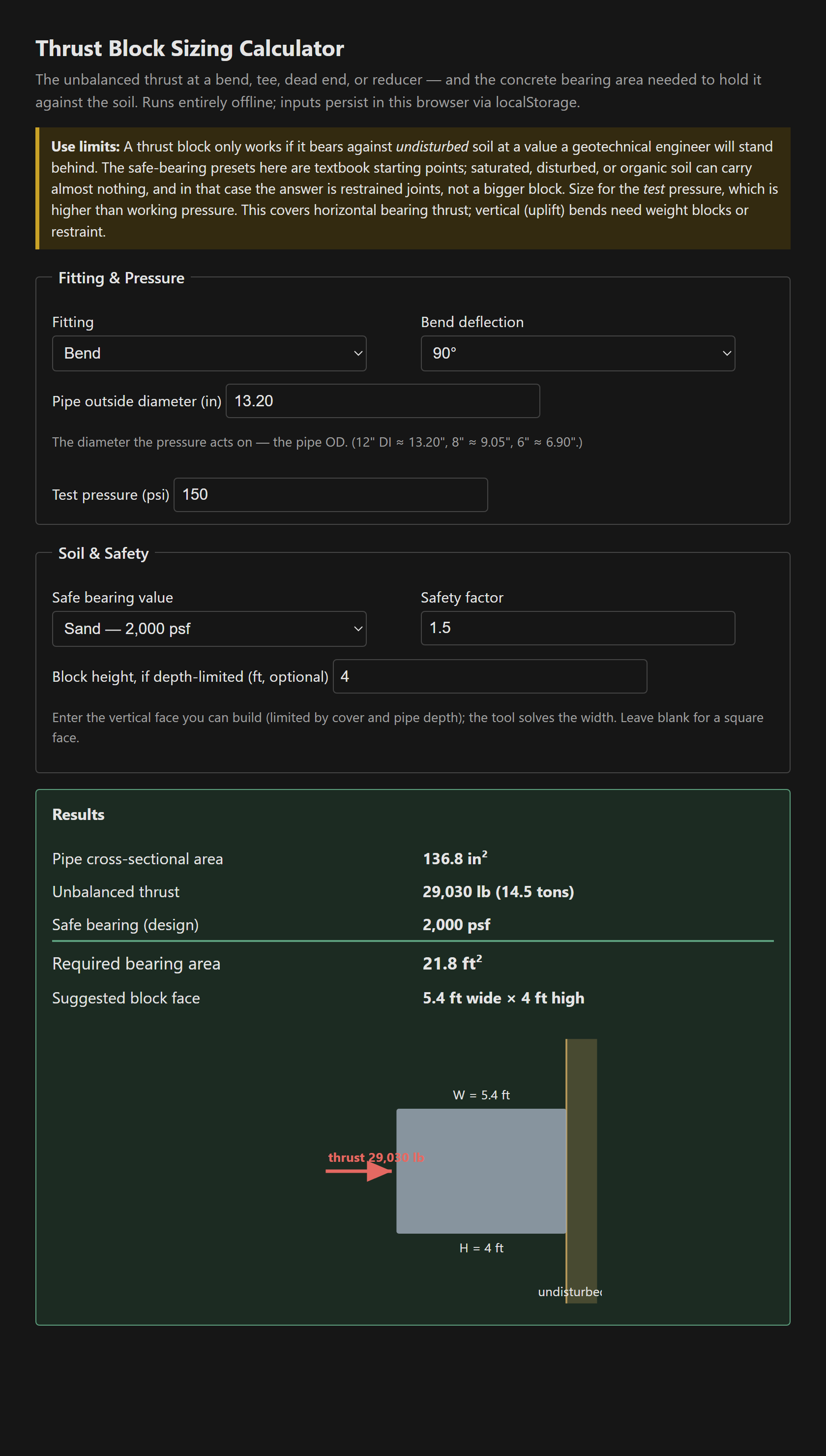
Internal pressure acts on the pipe's full bore, A = π/4 · OD², and the unbalanced thrust depends on the fitting: a bend is 2 · P · A · sin(θ/2), a dead end or tee branch is P · A, a reducer is P · (A₁ − A₂). Because pounds per square inch times square inches is pounds, the thrust comes straight out in pounds. The block's face area is then Ab = T · SF / Sb against the soil's safe bearing value. The tool draws the required face to scale, bearing against undisturbed soil, with the thrust pushing into it.
The block is only as good as the soil — know when to switch
The whole calculation hangs on one number the calculator can't give you: the soil's safe bearing value. The presets are textbook starting points, but a thrust block bears against undisturbed soil poured against the trench wall — never backfill — and in saturated, organic, or disturbed ground that value collapses toward zero. Watch what that does: as the safe bearing shrinks, the required face grows without bound, and you end up drawing a block the size of a car. That's not a sizing problem, it's a signal. When the soil won't carry the thrust, the answer isn't a bigger block; it's restrained joints, which carry the force in the pipe wall over a calculated restrained length and don't care what the soil face can bear. The tool makes the collapse explicit: pick the muck/peat preset and it stops giving you an area and tells you to restrain instead.
Blocking field notes
- Size for test pressure, not working pressure — the joint sees its highest load during the hydrostatic test, and that's the case that has to hold.
- The thrust acts along the bisector of the bend, outward; the block goes on the outside of the bend, poured against the undisturbed wall.
- Keep concrete off the joint and bolts. The fitting has to stay accessible and repairable — bear on the body, wrap the joint.
- Vertical bends that lift need a weight block or restraint, not a bearing block — this sizes the horizontal bearing case.
- At larger sizes, price the block against restrained joints anyway; restraint is often cheaper, more reliable, and doesn't need a geotech to bless a bearing value.
Single static file, vanilla JS, everything persisted in localStorage and nothing leaving the browser.
The tool: Thrust Block Sizing Calculator.
References
- [1] DIPRA — Thrust Restraint Design for Ductile Iron Pipe.
- [2] AWWA M41 (ductile iron) and Uni-Bell PVC design guidance — thrust blocking and restraint.