Computing Bypass Pumping Total Dynamic Head with Hazen-Williams
The Problem
When you set up a temporary sewer bypass, the rental house hands you a pump curve and asks what head you are pumping against. If you guess low, the pump can't keep up and the manhole you are protecting overflows. If you guess high, you rent a bigger pump than you need and pay for it every day it sits on site. The honest answer is a total dynamic head number: static lift plus friction loss through however many hundred feet of lay-flat hose or fused HDPE you ran down the shoulder.
Friction loss is where people wave their hands. It is very sensitive to diameter — the loss term goes as roughly the fifth power of the bore — so using nominal pipe size instead of the actual inside diameter, or forgetting that a DR 11 HDPE wall eats a real chunk out of a 12-inch pipe, throws the whole estimate off.
The Approach
The tool runs Hazen-Williams in the customary GPM/inch form, friction slope in feet of head per 100 ft of pipe:
h_f = 0.2083 × (100/C)^1.85 × Q^1.85 / d^4.8655
with velocity as V = 0.4085 × Q / d². Static lift and discharge static head get added on top of friction and a percentage minor-loss allowance for fittings, and the result converts to psi at 0.4331 psi/ft. The C-factor is a dropdown of the values you actually meet in the field — 150 for new HDPE, 140 for rubber discharge hose, on down — and there is a lookup of real HDPE inside diameters by DR so nobody has to type nominal-minus-the-wall from memory [2].
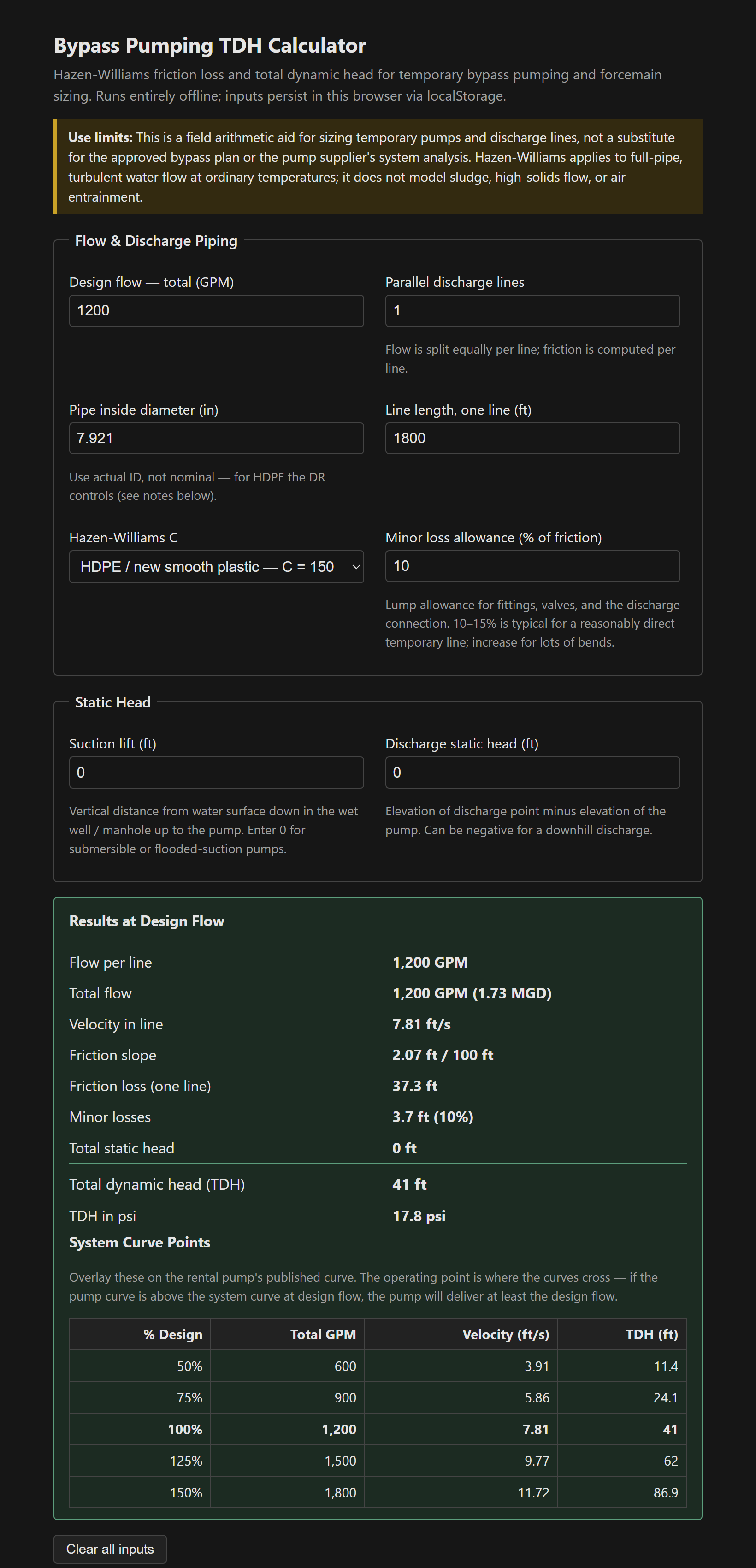
The part I find most useful on site is the system-curve table. It recomputes velocity and TDH at 50/75/100/125/150% of design flow, so instead of a single number you get five points to lay over the pump's curve. Where the two curves cross is the operating point — if the pump curve sits above the system curve at design flow, you know you have margin before you ever start the engine.
Velocity guardrails the tool warns on
- Below ~2 ft/s a sewage bypass line silts up — solids settle, grease and rags accumulate, and you get slug discharges. Many specs want 2.5–3.5 ft/s.
- Above ~8–10 ft/s friction climbs steeply, restrained fittings see high thrust, and hose whip becomes a real hazard. Usually cheaper to go up a pipe size than to buy the head.
- Systems sized for peak flow spend most of the day well below peak — check velocity at average flow, not just the design point.
Hazen-Williams assumes full-pipe, turbulent, ordinary-temperature water. It does not model sludge, high solids, or air entrainment, so this is a sizing aid, not a substitute for the approved bypass plan or the supplier's own analysis. Single file, vanilla JS, inputs persisted in localStorage.
The tool: Bypass Pumping TDH Calculator.
References
- [1] Hazen-Williams empirical formula, standard form per the Ten-State Standards and common hydraulics references (e.g. Lindeburg, Civil Engineering Reference Manual).
- [2] Plastics Pipe Institute, Handbook of Polyethylene Pipe — HDPE dimensions and C-factor guidance. https://plasticpipe.org/
- [3] Manufacturer pump curves — verify the operating point against the published curve for the specific rental unit.